
Steel is the material of choice for a large number and very diverse industrial applications. Surface qualities along with other properties are the most important quality parameters, particularly for flat-rolled steel products. Traditional manual surface inspection procedures are awfully inadequate to ensure guaranteed quality-free surface.
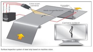
To ensure stringent requirements of customers, automated vision-based steel surface inspection techniques have been found to be very effective and popular during the last two decades. Cameras, Optics, specific Lighting, Software Algorithms to differentiate defects played and playing a key role in identification of surface defects. Steel as the inspection to be done on a large width and for smaller defect sizes, high resolution on cameras become essential. Also, Steel inspection is normally better to do on Motion and hence the Line Scan Cameras play a bigger part due to its one-line acquisition for larger widths and length can be dictated through software for any number of lines and also the high-speed line rate.
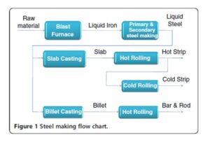
iron and steel making plant produces liquid iron in blast furnace with iron ore, coke, sinter and flux as input. Liquid iron is converted to liquid steel with specified constituent by primary and secondary steel making processes. Liquid steel is continuously cast into slabs and billets. Slabs are of rectangular cross-section with different dimensions.
Importance of surface quality of steel products, particularly that of cold-rolled steel assumed importance since 1980s primarily due to demands from automotive car makers. In course of time, hot strip surface quality, and in recent times, surface quality of structural products like rods/bars have assumed significant importance.
Traditionally manual inspection is done either a person watching and checking the steel for defects through naked eye randomly or seeing the video of the entire steel on a monitor. In hot strips, the strip is allowed to be cooled for few specific times and then a person walks on it with protective cloths to inspect the surface. This is again not good for the humans and also a crude method and effectiveness will be based on the persons ability and health conditions.
Broadly, steel surfaces can be categorised in flat and long products.
Flat product surfaces can further be classified as follows:
– Slab/billet: both are produced by continuous casting process from liquid steel and have some similarity with respect to surface and internal conditions. Surface is scale covered and more grainy.
– Plates are produced by reheating a slab at about 1,250°C and rolled subsequently. The surface is oxidised and comparatively even with respect to that of slab.
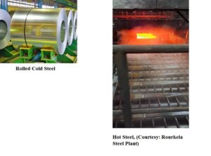
– Hot strips are produced by reheating a slab at about 1,250°C and rolling in multiple rolling stands to reduce the thickness to desired value. The strip surface is oxidised. However, due to high rolling force, the surface granularity of hot strip is considerably reduced compared to slab.
– Cold strips are produced by rolling hot strips in cold rolling mill after pickling process (which removes the oxide layer and cleans the surface). Thus, the surface of cold strips is not oxidised, and the surface is quite smooth due to very high rolling forces used in cold deformation process.
– Coated strip (galvanised, tinned)/finished stainless strip surfaces are highly reflective in nature.
Long product surfaces can further be classified as follows:
Rods/bars are produced from billet by hot rolling process, and their surface is fairly oxidised. Further, the surface is also not flat, and therefore, angle of reflection varies towards the periphery thus producing nonuniform image intensity. Other long products like angles, channels, heavy structural, rails etc. are produced from billet/bloom. They are of complex cross-section and require special lighting and camera arrangements.
Camera Arrangements to capture Steel surface:
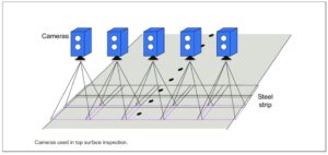
a) Area Scan approach: To capture a long and wide steel surface , due to non-high resolution camera availability, mostly multiple Area scan cameras are used to capture and process areas of steel. These cameras normally capture steel in non-motion or at a very slow motion. These camera pictures would be either stitched or separately used for inspection there by taking note of overlapping of images between cameras. The cameras have to be installed on top and bottom if both the surfaces to be inspected. Portions of steel can be moved across the camera array for inspection. Resolution of cameras would be decided based on the total width to be seen by that particular camera and also the size of the defect to be identified.
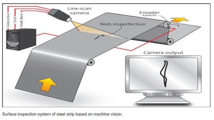
b) Line Scan Camera Approach:
This approach allows inspection by one camera with one line scan sensor and builds the frame while steel moves beneath the camera according to the speed of the movement of steel. This would generate very large images and can be inspected as parts or total image depending up on the algorithm and host system capabilities. Line Scan cameras are available up to 32K pixels and also in more than 200KHz line rate allowing any speed any accuracy checking of the defects.
For both the camera setup Lights would play a major part and the color of the light to be selected according to the reflection of steel surface, defects nature and surface finish of the steel.
Optics and Lighting to cover such wide areas would prove sometimes more expensive than cameras. Lights made of Xeon, Fluorescence, halogen, LED are used. Flicker free and also proper power lights are needed. Optical filters on cameras or optics or on Lights to avoid or allow specific wave lengths will also be needed.
Algorithms that are used for Inspection:
Software pre-processors and algorithms like Morphological operators, Edge Detectors, Crawlers, Filters, Tresholding and Blob Analysis, Statistical analysis etc., are used to detect and classify steel defects.
With advent of AI (deep learning) the defects can also trained for classification, segmentation and anomaly detection.
Defects normally can be classified as below:
Slab: cracks (on surface and corner), pitting (pinhole and blowhole), scratch, scarfing defects.
Plate: crack scratch, seam.
Billet: corner crack, line defect, scratch.
Hot-rolled strip: hole, scratch, rolled in scale, crack, pits/scab, edge defect/coil break, shell, lamination, sliver.
Cold-rolled strip: roll marks, holes, scratches, dark/ black line, heat buckle, rust, sliver, scale, roll mark, oil spot, serrated edge, wrinkle, inclusion, shell, pimple, oxide scale, lamination.
Stainless steel: holes, shells, inclusions, blowhole, scales, scratches, pimples, roll mark.
Wire rod/bar: crack, spot, dark line, laps, overfill, scratches, gorges, seams, slivers, roll mark.
3D is not used conventionally with Steel Inspection due to size and also complexity in Intensity based Imaging.
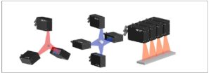
LASER Lines and Triangulation methods have evolved to see a surface for its defects both in X and Z. Y can be seen when the object to be inspected is moved.
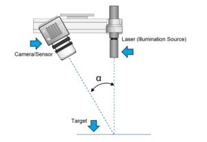
These triangulation methods as shown in the picture would make the LASER line fall on the object and view the object in 45 degrees or so in angle to see both X and Z. As there is no intensity-based imaging it only shows the PROFILE of the image, and the camera will be filtered to receive only the LASER Line as Image. In common these profiles were still handled as Intensity images to calculate the lengths and heights.
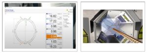
Later with the introduction of 3D LASER Line profiler sensors, the calibrated devices which can show the X and Z values on a 3D profile with Micron level, the defect inspection based on height as defect from the original surface or depth as defect from the Surface level can be detected.
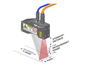
There are a number of techniques available for 3D imaging. There are 3D laser profilers that uses a laser triangulation technique to deliver high resolution height measurements. The profiler emits a laser onto an object of interest; the reflection’s position in the sensor’s field of view allows the scanner to triangulate the point in space at which the laser hits the object.
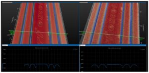
Above picture shows both profile output and Surface output of a 3D laser profilers in India.
Many 3D profilers can be used as one side to another or one after another or on all 4 directions of the object as top, bottom and two sides. The 3D profiler sensors can be selected as per specifications of X res and Z resolutions and if movement of object involved then Y – Profiling speed.
Multiple 3D Profiler arrangements for Inspecting steel of larger widths or create 3D of the entire component or object to be inspected.
These can be used in steel surface inspection to detect pits and holes on surfaces, deep scratches that create a micron level depth, corrosion that does reflect the LASER light as the normal surface does etc. As these devices are already calibrated then X and Z values of each 3D point can be read in Microns to compute the size and identify or classify defects.
These devices can be used to gauge the edges also.
In rebar steel ribs and other parametric computation these can be used.
LASERs of different colors based on the Surface and nature of the steel like hot, cold etc., can be used. Normally Blue LASER s is used for Hot Steel Inspection, Green lights are used for Cold Steel and many times Red Lasers are also used.
Unlike Bright Field or Dark Field Light systems used with cameras there is no need of complex Flat field corrections and spatial corrections required. Distances of the 3D profilers from the object are fixed as near and far distances.
Online Solutions (Imaging) Pvt. Ltd., Chennai working with Steel giants of India like Steel Authority of India, TATA Steel etc., for different kind of Steel inspection projects as consultant on component selection and also as component supplier for more than 2 decades now.
Online Solutions (Imaging) Pvt. Ltd., Chennai represents Teledyne DALSA (for their Line Scan and area scan cameras, 3D profilers, software), Navitar for their lenses, Moritex for their lighting, Z LASER for their LASERs in India and provides all kind of solutions and components based on the products of these companies.
Online Solutions is also works with small to medium level system builders and integrators of specific Steel inspection projects.
Note: This write up is prepared by collecting information from EURASIP Journal on Image and Video Processing ( a paper on review of Vision based Steel Surface Inspection Systems) (available for download for no cost) and internet images/ information, information from manufacturers like Teledyne DALSA , other manufacturers not named and our own concepts on these inspection systems. This write up is only for information purposes and not for any commercial purposes. All readers of this article/blog are requested not to use this information for any commercial purposes without getting consent from all mentioned here. This article if found objectionable, the same can be raised to [email protected] or [email protected] for corrections/modifications or total removal of contents.
We'll be glad to help you! Please contact our Sales Team for more information.
We'll be glad to help you! Please contact our Sales Team for more information.